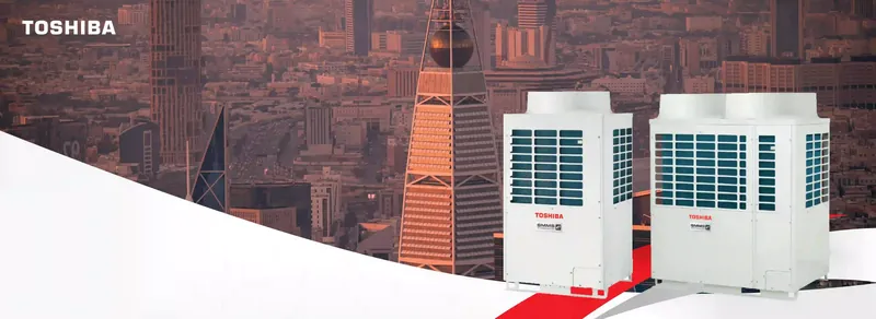
VRF systems are among the most flexible heating and cooling solutions for hotels. They provide individual temperature control, high seasonal efficiency, modular installation and centralised system management.
However, hotel HVAC systems should not be assessed solely on capacity, energy efficiency and initial cost. One of the principal design considerations is occupant safety in the event of a refrigerant leak.
This is particularly important in hotel bedrooms, which are generally relatively small, enclosed spaces where occupants may be asleep and unable to respond immediately to an alarm or a change in environmental conditions.
The EN 378 series establishes safety and environmental requirements for refrigerating systems and heat pumps. For the designer, the central question is:
If a refrigerant leak occurs, could the resulting concentration exceed the applicable limit in the smallest space served by the system?
The answer does not depend solely on the selected equipment. It is determined by the combination of refrigerant type, total system charge, room volume, pipework architecture and the safety measures incorporated into the design.
What EN 378 actually requires
EN 378 does not automatically prohibit the use of VRF systems in hotel bedrooms. Nor does it require the complete removal of refrigerant from every occupied space in all circumstances.
The standard requires the system to be designed so that risks to people, property and the environment remain within acceptable limits.
Each project therefore requires an assessment of:
- the safety classification of the refrigerant;
- the total refrigerant charge and the quantity that could potentially be released;
- the volume of the smallest relevant occupied space;
- the occupancy category of the building;
- the number and characteristics of occupants;
- the location of equipment and refrigerant pipework;
- the configuration and segmentation of the refrigerant circuit;
- leak detection and alarm arrangements;
- automatic isolation or refrigerant recovery measures;
- natural or mechanical ventilation;
- manufacturer requirements and applicable local legislation.
Compliance with EN 378 must therefore be demonstrated through engineering calculations and documented safety measures — not merely through the selection of a particular brand or equipment model.
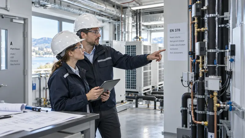
Why the smallest room is critical
In a VRF system, refrigerant circulates from the outdoor unit to the indoor units. If a leak occurs, a quantity of refrigerant may be discharged into a single occupied space.
The assessment must therefore not be based on the total floor area of the hotel. The designer must identify the smallest space into which refrigerant could be released under the relevant leakage scenario.
The following must be established:
- The effective volume of the room.
- The total refrigerant charge of the circuit.
- The quantity that could potentially be released into the room.
- The applicable limit for the selected refrigerant.
- The protective measures activated in the event of a leak.
If the applicable criterion is not satisfied, the system design must be modified or supplemented with additional mitigation measures.
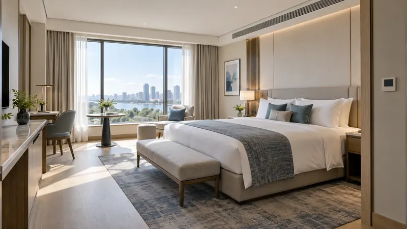
How compliance can be achieved
Depending on the system and its configuration, appropriate measures may include:
- reducing the refrigerant charge;
- dividing the installation into smaller circuits;
- modifying the refrigerant pipework arrangement;
- installing automatic valves to isolate the affected branch;
- recovering or pumping refrigerant back to the outdoor unit;
- installing refrigerant leak detectors in individual rooms;
- providing audible and visual alarms;
- automatically stopping the affected system;
- activating mechanical ventilation;
- selecting a hydronic system in which water, rather than refrigerant, circulates through occupied rooms.
There is no single solution suitable for every hotel. The appropriate configuration should be selected according to the size of the property, room typologies, architectural constraints, available budget, maintenance strategy and the operator's requirements.
Toshiba solutions for refrigerant risk management
Toshiba offers VRF systems for hotels and commercial buildings, together with dedicated components for detecting and managing potential refrigerant leaks.
Subject to the selected series and final configuration, a Toshiba solution may include:
- dedicated refrigerant leak-detection sensors;
- local and central alarm functions;
- valves for isolating affected sections of pipework;
- automatic shutdown of indoor units;
- refrigerant pump-back to the outdoor unit;
- integration with central controls;
- outputs to ventilation systems or other building services;
- verification of the installed refrigerant charge through the relevant selection tools.
This approach is intended to reduce the amount of refrigerant that could be released into an occupied room and to initiate automatic safety actions when a leak is detected.
The design must be based on accurate project data, including actual pipe lengths, pipe diameters, additional refrigerant charge, room dimensions and volumes, sensor locations, and the locations and functions of isolation valves.
Compliance must be confirmed for the final system configuration using Toshiba's official technical documentation, applicable standards and the project-specific engineering assessment.
Hisense VRF solutions for hotel projects
The Hisense HVAC portfolio includes VRF systems designed for hotels, commercial buildings and other multi-zone applications.
Depending on the selected series and configuration, Hisense VRF systems may provide:
- individual room temperature control;
- modular operation;
- centralised management;
- flexible pipework design;
- backup functions supporting continuity of operation;
- refrigerant recovery functions for installation or maintenance purposes in relevant product series;
- integration with building management systems.
When a Hisense VRF system is proposed for hotel bedrooms, the designer must assess the refrigerant charge against the volume of the smallest relevant room and determine the required safety measures.
Where leak detection, isolation, ventilation or other protective functions are required, they must be designed and documented in accordance with the technical manuals for the selected Hisense series, the final refrigerant circuit configuration, EN 378, other applicable product and safety standards, and national or local regulatory requirements.
It should not be assumed that every function is available across all Hisense product series or market configurations. Final equipment and safety-component availability must be verified with ERAM Group's technical team and the manufacturer's official documentation.
The role of Systemair: ventilation, air treatment and hydronic solutions
Systemair complements hotel HVAC projects in another critical area: ventilation, indoor air quality and, where a hydronic architecture is selected, the distribution of heating and cooling through water-based systems.
Depending on the project requirements and product availability, the Systemair portfolio may include:
- air-handling units;
- supply and extract fans;
- ventilation solutions for hotel rooms and common areas;
- ventilation for corridors and technical spaces;
- bathroom and ancillary-area extraction;
- pressure-control and air-management systems;
- fan-coil units for hydronic systems;
- air-distribution and control components.
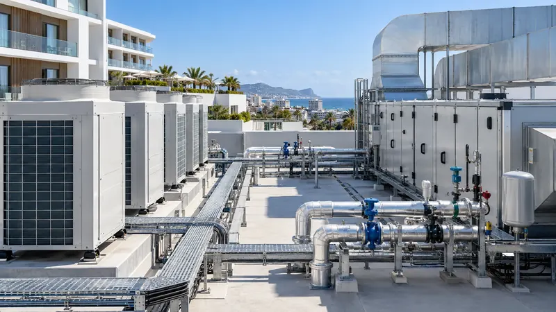
Where EN 378 or the project risk assessment requires mechanical ventilation as a protective measure, the solution must not be treated as an isolated fan installation. The complete safety function must be designed, including:
- the required airflow rate;
- supply and extract locations;
- grille positioning;
- automatic activation logic;
- signals from the refrigerant detector;
- electrical supply and operation during an alarm condition;
- safe discharge of extracted air;
- interaction with the fire strategy and building management system.
Where the project objective is to remove refrigerant pipework from hotel bedrooms, a hydronic solution using central thermal generation and Systemair fan-coil units may also be assessed. In such a configuration, water circulates through the bedrooms instead of refrigerant.
This type of installation should not automatically be described as “Hybrid VRF”. It is a hydronic system architecture that must be designed and compared with VRF alternatives on the basis of the project's actual requirements.
Three approaches for hotel projects
Option 1: VRF with refrigerant charge within the permitted limit
This approach may be used where the engineering assessment demonstrates that the potentially releasable refrigerant charge does not exceed the applicable limit for the relevant room.
It may provide the simplest solution, but it still requires:
- documented calculations;
- confirmation of the final refrigerant charge;
- accurate pipework data;
- verification for every relevant room type;
- reassessment of any installation changes.
Option 2: VRF with active safety measures
Where the basic charge-to-room-volume criterion is not satisfied, additional measures may include:
- refrigerant leak detection;
- local and central alarms;
- automatic isolation;
- refrigerant pump-back or recovery;
- mechanical ventilation;
- integration with central controls or the BMS.
Toshiba and Hisense VRF systems should be selected according to the technical capabilities and available safety components of the specific product series. Systemair can provide the ventilation and air-treatment elements where these form part of the agreed safety strategy.
Option 3: Hydronic system with no refrigerant in the bedrooms
Under this configuration, heating and cooling are generated centrally, while water is distributed to fan-coil units in the hotel rooms. Systemair equipment may form part of this hydronic architecture, subject to product suitability and availability for the relevant market.
This approach:
- removes refrigerant from hotel bedrooms;
- concentrates the principal refrigeration equipment in technical areas;
- may simplify the refrigerant risk assessment for occupied rooms;
- requires complete hydraulic system design;
- requires condensation control, insulation, balancing and water-quality management;
- may require more technical space and larger service risers.
The comparison should extend beyond initial cost
A professional evaluation should consider:
- initial capital expenditure;
- seasonal energy efficiency;
- refrigerant type and installed charge;
- detectors, alarms and isolation valves;
- mechanical ventilation requirements;
- BMS and central-control integration;
- commissioning and functional testing;
- periodic sensor calibration;
- lifecycle maintenance costs;
- spare-parts and service availability;
- disruption caused by maintenance inside occupied rooms;
- operational continuity and redundancy;
- flexibility for future refurbishment or expansion;
- future regulatory requirements affecting refrigerants.
A solution with a lower initial equipment cost may require additional investment in leak detection, isolation, ventilation and lifecycle maintenance. Conversely, a hydronic solution may involve higher initial investment and greater space requirements, but remove refrigerant from the bedrooms and reduce safety-system complexity within occupied areas.
ERAM Group's integrated approach
ERAM Group treats a hotel HVAC installation as an integrated system rather than as an isolated equipment-selection exercise.
By combining the Toshiba, Hisense and Systemair portfolios, the project approach may include:
- Analysis of thermal loads and comfort requirements.
- Identification of the smallest rooms and other critical spaces.
- Calculation of the installed refrigerant charge.
- Assessment against EN 378 and other applicable requirements.
- Comparison of VRF and hydronic alternatives.
- Selection of detection, isolation and ventilation measures where required.
- Integration of air conditioning, ventilation and control systems.
- Technical support during installation and commissioning.
- Planning for maintenance, spare parts and after-sales service.
This approach enables investors, consultants and hotel operators to select a solution based on safety, performance, lifecycle cost and the building's actual operating requirements.
Conclusion
EN 378 does not prescribe one technology or one equipment brand. It requires the refrigerant-related risk to be identified, calculated and controlled.
For a hotel project, this means establishing:
- how much refrigerant could be released;
- where it could be released;
- what concentration could result;
- which protective measures would be activated;
- how those measures would be tested and maintained throughout the system's operational life.
Toshiba and Hisense provide VRF solutions that can be designed for hotel applications, while Systemair complements the installation with ventilation, air-treatment and hydronic options.
The optimum solution is not determined solely by the equipment. It results from integrated engineering, documented calculations and proper coordination between air conditioning, ventilation, controls, safety systems and hotel operations.
Technical notice
This article is provided for general professional information. It does not replace a project-specific engineering design, the official text of the applicable standard, manufacturer instructions or verification by the responsible qualified engineer.
The availability and suitability of individual functions, accessories and safety components must be confirmed for the selected product model, series and market.
Reference sources
- BSI Knowledge — BS EN 378-1:2016+A1:2020
- Toshiba — Refrigerant leak detection
- Hisense HVAC — VRF products and solutions
- Systemair — Ventilation and air-handling solutions
- EUR-Lex — Regulation (EU) 2024/573 on fluorinated greenhouse gases
ERAM Group — integrated HVAC solutions for hotels, commercial buildings and complex projects, supported by the Toshiba, Hisense and Systemair portfolios. For project-specific advice, contact our technical sales team at sales@eram-group.net.